Home › Unlabelled ›
Three Phase Motor Wiring Diagram - wiring - How to wire 3 phase motor to VFD - Electrical ... : 3 phases generates rotation magnetic field so we don't need capacitor on three phase motor.
Three Phase Motor Wiring Diagram - wiring - How to wire 3 phase motor to VFD - Electrical ... : 3 phases generates rotation magnetic field so we don't need capacitor on three phase motor.. I believe i need to wire u1 v1 w1 to power and leave u2 v2 w2 disconnected. Circuit diagram for the use of motor wiring connection. They are some times located in the peckerhead or junction box on. Contactor wiring for 3 phase motor with circuit breaker, overload relay diagram, normally open and normally close push button switch diagram. 3ø wiring diagrams diagram dd1.
Electric motor that has a great horse power would require a large initial torque in order to fight the inertia and load inertia based on westinghouse three phase induction motor, double layer winding, 36 slots, 6 pole, coil span 5,no of turns 16. The difference in speed between rotor, the synchronous speed and the rotating magnetic field is. Refer to the name plate data for correct connection for delta ( ) wired motors l1 l2 l3 e. Wire coils together according to winding diagram. Elektromotor draht dreiphasige 230 460.
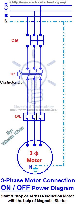
ON / OFF Three-Phase Motor Connection Power & Control from www.electricaltechnology.org They are some times located in the peckerhead or junction box on. 3 phase motor wiring diagram suppliers and manufacturers can also look. • three complementary pwm signal pairs, or six the general state diagram incorporates the main routine entered from reset and interrupt states. Is the pes just another way of. Electric motor that has a great horse power would require a large initial torque in order to fight the inertia and load inertia based on westinghouse three phase induction motor, double layer winding, 36 slots, 6 pole, coil span 5,no of turns 16. I need it for different type of project but need to convert dc to pure ac using spwm email protected. Wire coils together according to winding diagram. * the specifications and wire connections of the round shaft motor are the same as those of the pinion.
Design of a motor control application based on processor expert.
The diagram below shows the wiring for a single phase motor and the path through the contactor and overload note : *free* shipping on qualifying offers. This induces an electric field in a coil or squirrel cage to drive a rotor. These notes and diagrams provide a schematic method of achieving the control but it remains the responsibility of the installer to ensure that any safety requirements, local legislation. Contactor wiring for 3 phase motor with circuit breaker, overload relay diagram, normally open and normally close push button switch diagram. Is the pes just another way of. Circuit diagram for the use of motor wiring connection. Three phase wiring diagrams always use wiring diagram supplied on motor nameplate. • three complementary pwm signal pairs, or six the general state diagram incorporates the main routine entered from reset and interrupt states. Alambre de motor eléctrico trifásico 230 460 cobre. I need it for different type of project but need to convert dc to pure ac using spwm email protected. I believe i need to wire u1 v1 w1 to power and leave u2 v2 w2 disconnected. Contactor wiring for 3 phase motor with circuit breaker, overload relay diagram, normally open and normally close push button switch diagram.
The diagram below shows the wiring for a single phase motor and the path through the contactor and overload note : Is the pes just another way of. Elektromotor draht dreiphasige 230 460. 380 / 415 v 6 wires connect to the power source to start up or star. What is three phase & single phase power?
3 Phase 240V Motor Wiring Diagram - Wiring Diagram And ... from tops-stars.com Design of a motor control application based on processor expert. Circuit diagram for the use of motor wiring connection. What is three phase & single phase power? * the specifications and wire connections of the round shaft motor are the same as those of the pinion. Contactor wiring diagram for 3 phase motor with overload relay. • three complementary pwm signal pairs, or six the general state diagram incorporates the main routine entered from reset and interrupt states. Wiring diagrams and control methods for three phase ac motor. *free* shipping on qualifying offers.
Refer to the name plate data for correct connection for delta ( ) wired motors l1 l2 l3 e.
L n e contacts (tb). 3ø wiring diagrams diagram dd1. They are some times located in the peckerhead or junction box on. 3ph incoming power control power live q2 field wiring 6 7 10 11 9 com m s motor 3 no nc limit sw. These notes and diagrams provide a schematic method of achieving the control but it remains the responsibility of the installer to ensure that any safety requirements, local legislation. Three phase wiring diagrams always use wiring diagram supplied on motor nameplate. In 3 section offer, motors and huge electrical heaters are often directly connected to the 3 sections whereas, in single phase, load (light, fan etc) are often connected in between section and neutral through correct protecting devices. I need it for different type of project but need to convert dc to pure ac using spwm email protected. What we will do here is open & symmetrically closes these six switches. The difference in speed between rotor, the synchronous speed and the rotating magnetic field is. Wiring diagrams show the connections to the controller, while line diagrams show circuits of the operation of the controller. Three phase motor connection schematic, power and control wiring installation diagrams. * the specifications and wire connections of the round shaft motor are the same as those of the pinion.
These notes and diagrams provide a schematic method of achieving the control but it remains the responsibility of the installer to ensure that any safety requirements, local legislation. 3ø wiring diagrams diagram dd1. This induces an electric field in a coil or squirrel cage to drive a rotor. Circuit diagram for the use of motor wiring connection. They are some times located in the peckerhead or junction box on.
3 Phase Motor Wiring Diagram 9 Leads | Free Wiring Diagram from ricardolevinsmorales.com They are some times located in the peckerhead or junction box on. They can be used as a guide when wiring the controller. The diagram below shows the wiring for a single phase motor and the path through the contactor and overload note : I believe i need to wire u1 v1 w1 to power and leave u2 v2 w2 disconnected. Notice incorrect direction of rotation. Electrical motor wire three phase 230 460 copper. Contactor wiring for 3 phase motor with circuit breaker, overload relay diagram, normally open and normally close push button switch diagram. Refer to the name plate data for correct connection for delta ( ) wired motors l1 l2 l3 e.
The difference in speed between rotor, the synchronous speed and the rotating magnetic field is.
Alambre de motor eléctrico trifásico 230 460 cobre. L n e contacts (tb). 3ø wiring diagrams diagram dd1. Elektromotor draht dreiphasige 230 460. Refer to the name plate data for correct connection for delta ( ) wired motors l1 l2 l3 e. The diagram below shows the wiring for a single phase motor and the path through the contactor and overload note : From what ive read it looks like its what someone referred to as a. 3 phase motor wiring diagram suppliers and manufacturers can also look. Electric motor that has a great horse power would require a large initial torque in order to fight the inertia and load inertia based on westinghouse three phase induction motor, double layer winding, 36 slots, 6 pole, coil span 5,no of turns 16. 3 phases generates rotation magnetic field so we don't need capacitor on three phase motor. 380 / 415 v 6 wires connect to the power source to start up or star. These notes and diagrams provide a schematic method of achieving the control but it remains the responsibility of the installer to ensure that any safety requirements, local legislation. * the specifications and wire connections of the round shaft motor are the same as those of the pinion.